1. Introduction

Did you ever think that how the street lights automatically turn ON in the night and turn OFF automatically at morning? Is there any person who comes to ON/OFF these lights? The following circuit that described below which perform this job automatically. This circuit employed the output from an uncomplicated light/dark activated circuit and oblige a relay in its output which can be further attached to switch ON/OFF a street light and electrical application in a household also.Automatic street light control is used to control the street lights(Turn on and off based on the light).It is a simple and powerful concept, which uses transistor (BC 547 NPN) as a switch to switch ON and OFF the street light system automatically.It automatically switches ON lights when the sunlight goes below the visible region of our eyes. (e.g in evening after Sunset). it automatically switches OFF lights when Sunlight fall on it ( i.e on LDR ) e.g in morning, by using a sensor called LDR (Light Dependent Resistor) which senses the light just like our eyes.
1 .INTRODUCTION. The idea of designing a new system for the streetlight that do not consume huge amount of electricity and illuminate large areas with the highest intensity of light is concerning each engineer working in this field. Providing street lighting is one of the most important and expensive responsibilities of a city. Lighting can account for 10–38% of the total energy bill in typical cities worldwide [1]. Street lighting is a particularly critical concern for public authorities in developing countries because of its strategic importance for economic and social stability. Inefficient lighting wastes significant financial resources every year, and poor lighting creates unsafe conditions. Energy efficient technologies and design mechanism can reduce cost of the street lighting drastically. Manual control is prone to errors and leads to energy wastages and manually dimming during mid night is impracticable. Also, dynamically tracking the light level is manually impracticable. The current trend is the introduction of automation and remote management solutions to control street lighting [2]. There are various numbers of control strategy and methods in controlling the street light system such as design and implementation of CPLD based solar power saving system for street lights and automatic traffic controllers. In this paper two kinds of sensors will be used which are light sensor and photoelectric sensor. . LDR, which varies according to the amount of light falling on its surface, this gives an inductions for whether it is a day-night time, the photoelectric sensors are placed on the side of the road, which can be controlled by microcontroller PIC16f877A. The photoelectric will be activated only on the night time. If any object crosses the photoelectric beam, a particular light will be automatically ON. By using this as a basic principle, the intelligent system can be designed for the perfect usage of streetlights in any place.
2 Automatic street light system circuit design .The system basically consists of a LDR, Photoelectric sensor, Power supply, Relays and Micro controller.
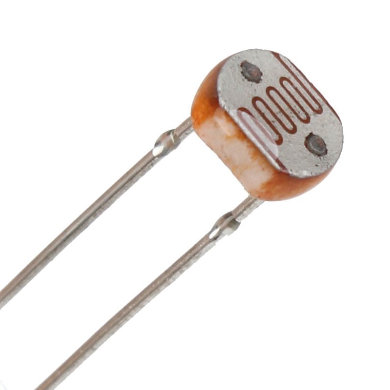
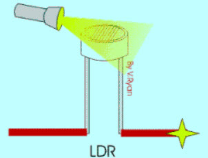
2.1 LDR .The theoretical concept of the light sensor lies behind, which is used in this circuit as a darkness detector. The LDR is a resistor as shown in Fig. 2, and its resistance varies according to the amount of light falling on its surface. When the LDR detect light its resistance will get decreased, thus if it detects darkness its resistance will increase.
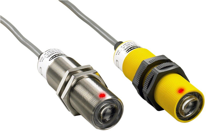
2.2 PHOTOELECTRIC SENSOR. To detect the movement in the street, the photoelectric sensors have been used in this paper, where emitter and receiver are in one unit as shown in Fig 3. Light from the emitter strikes the target and the reflected light is diffused from the surface at all angles. If the receiver receives enough reflected light the output will switch states. When no light is reflected back to the receiver the output returns to its original state. In diffuse scanning the emitter is placed perpendicular to the target. The receiver will be at some angle in order to receive some of the scattered (diffuse) reflection.
2.3Regulated power supply. Usually, we start with an unregulated power supply
ranging from 9volt to 12volt DC. To make a 5vol power supply, KA8705 voltage regulator IC as shown in Fig. 4 has been used.
Fig. 4 Power supply regulator
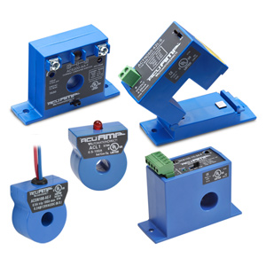
2.4 Relays . Relays are remote control electrical that are controlled by another switch, such as a horn switch or a computer as in a power train control module. Relays allow a small current flow circuit to control a higher current circuit. Several designs of relays are in use today, 3-pin, 4-pin, 5-pin, and 6-pin, single switch or dual switches. Relays which come in various sizes, ratings, and applications, are used as remote control switches. Fig. 5 shows different types of relays.
3. RESULTS AND DISCUSSIONS The project aims were to reduce the side effects of the current street lighting system, and find a solution to save power. In this project the first thing to do, is to prepare the inputs and outputs of the system to control the lights of the street. The prototype as shown in Fig. 9 has been implemented and works as expected and will prove to be very useful and will fulfill all the present constraints if implemented on a large scale. Shows the street light system, from the figure it can be seen that, all lighting column are OFF, because there is no any object passes through the street, even though the weather is night. This is the idea of using the microcontroller to control each lighting column alone. When any object passes in front front specific photoelectric sensor the lighting column which connected to it will be turn ON automatically .

4 Conclusion This paper elaborates the design and construction of automatic street control system circuit. Circuit works properly to turn street lamp ON/OFF. After designing the circuit which controls the light of the street as illustrated in the previous sections. LDR sensor and the photoelectric sensors are the two main conditions in working the circuit. If the two conditions have been satisfied the circuit will do the desired work according to specific program. Each sensor controls the turning ON or OFF the lighting column. The street lights has been successfully controlled by microcontroller. With commands from the controller the lights will be ON in the places of the movement when it’s dark. furthermore the drawback of the street light system using timer controller has been overcome, where the system depends on photoelectric sensor. Finally this control circuit can be used in a long roadways between the cities.